Making air variable capacitors
*********************************************************
Once upon a time such things as "air variable capacitors" did not exist, and neither did unicorns nor flying elephants...
Here we are not trying to re-invent the wheel or vulcanize rubber on a kitchen pot, nevertheless, I've heard some rumors that air variable capacitors have gone the way of unicorns and flying elephants. Well not so fast, as making one only requires pen, paper, ruler, some aluminum sheet, threaded rod, nuts, plexiglass, tin snips, drill, hammer, file, and an open end wrench.
Lots of time and patience helps too. Watch me make one (or two).
This is also my first attempt at making air variable caps!
**********************************************************
As in any project, first state the goal:
300-500 pF, capable of handling at least 300 Watts RF, 1.8 to 30 MHz.
- Locate some scrap aluminum sheet, thick enough to make stiff capacitor plates.

- Look in the internet for capacitance formulas, decide on size, structure, shape.

- Make a trial cut, in this case, a stator plate.

- Define a master plate to use as a reference.
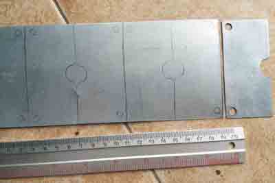
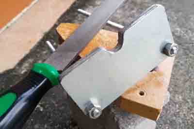
- Wear work gloves and use tin snips to cut enough plates as per calculated and desired capacitance. We started out with 20 stator plates. Drill holes to accommodate quarter inch threaded stock.

- Flatten the resulting plates.

- Tightly bolt all stator plates together and file the rough edges to achieve uniformity.
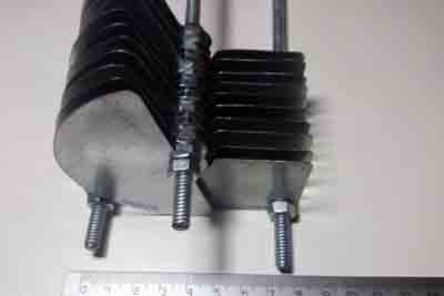
- Repeat for the rotor plates.


- Initial assembly to verify correct clearance. File excess off if too tight or too close.

- Used 5 mil thick Lucite (Acrylic) cut to 10 x 10 cm size for the end supports.

- Drill the Lucite supports per drawing dimensions.

- It will take several tries at assembly/disassembly to find the correct way of tightening all the nuts and plates together without binding or obstructions.


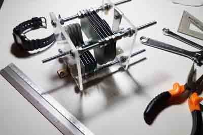
- Making solid and reliable electrical connections was also a challenge. Eventually, used spring loaded wiping contacts. This is expected to be a point of RF losses.

- Completed air variable capacitor pair.

- Lesson learned: next time, use aluminum from a food tray. It is easier to cut and less
likely to corrode.

*********************************************************
As with any project, at the end, state the conclusion:
Calculated capacitance was 600 pF (we suspected this was on the high side) for each unit, but after completion, actual capacitance was measured at 200 pF.
This means each unit has to be expanded to accommodate twice as many plates.
Have to review the cause of miscalculation, as the error was 66% on the low side and short of the 300 pF minimum.
*********************************************************
Back to Home Page